EP2602601A1 - System for monitoring a drive train - Google Patents
System for monitoring a drive train Download PDFInfo
- Publication number
- EP2602601A1 EP2602601A1 EP20120193457 EP12193457A EP2602601A1 EP 2602601 A1 EP2602601 A1 EP 2602601A1 EP 20120193457 EP20120193457 EP 20120193457 EP 12193457 A EP12193457 A EP 12193457A EP 2602601 A1 EP2602601 A1 EP 2602601A1
- Authority
- EP
- European Patent Office
- Prior art keywords
- primary
- shaft
- monitoring
- rotation
- kinematic chain
- Prior art date
- Legal status (The legal status is an assumption and is not a legal conclusion. Google has not performed a legal analysis and makes no representation as to the accuracy of the status listed.)
- Granted
Links
- 238000012544 monitoring process Methods 0.000 title claims abstract description 103
- 230000007257 malfunction Effects 0.000 claims abstract description 24
- 230000005540 biological transmission Effects 0.000 claims abstract description 23
- 238000000034 method Methods 0.000 claims abstract description 12
- 230000033001 locomotion Effects 0.000 claims description 19
- 230000003068 static effect Effects 0.000 claims description 14
- 230000008569 process Effects 0.000 claims description 2
- 238000010586 diagram Methods 0.000 description 8
- 238000001514 detection method Methods 0.000 description 7
- 238000006073 displacement reaction Methods 0.000 description 4
- 241001417494 Sciaenidae Species 0.000 description 3
- 230000004044 response Effects 0.000 description 3
- 230000008859 change Effects 0.000 description 2
- 230000008878 coupling Effects 0.000 description 2
- 238000010168 coupling process Methods 0.000 description 2
- 238000005859 coupling reaction Methods 0.000 description 2
- 241000233866 Fungi Species 0.000 description 1
- 230000004913 activation Effects 0.000 description 1
- 230000006978 adaptation Effects 0.000 description 1
- 230000032683 aging Effects 0.000 description 1
- 230000001174 ascending effect Effects 0.000 description 1
- 238000012550 audit Methods 0.000 description 1
- 239000004020 conductor Substances 0.000 description 1
- 230000007547 defect Effects 0.000 description 1
- 230000003287 optical effect Effects 0.000 description 1
- 238000012545 processing Methods 0.000 description 1
- 238000012549 training Methods 0.000 description 1
- 238000012795 verification Methods 0.000 description 1
Images


Classifications
-
- G—PHYSICS
- G01—MEASURING; TESTING
- G01M—TESTING STATIC OR DYNAMIC BALANCE OF MACHINES OR STRUCTURES; TESTING OF STRUCTURES OR APPARATUS, NOT OTHERWISE PROVIDED FOR
- G01M13/00—Testing of machine parts
- G01M13/02—Gearings; Transmission mechanisms
- G01M13/021—Gearings
Definitions
- the present invention relates to kinematic chain monitoring systems. More particularly, this type of system can be used for example to secure winches for handling loads.
- the present invention aims to provide at least in part a solution to the aforementioned problems.
- said system can control in a controlled time a trip output in case of malfunction of kinematic chain.
- said system due to its redundancy, still allows to quickly activate a trip output in case of malfunction of the driveline.
- a malfunction of the kinematic chain is declared in the event of exceeding at least a predetermined speed threshold on the primary or secondary shaft, and / or in case of desynchronism of the positions between the primary shaft and the secondary tree; so a fault in overspeed or desynchronism causes the kinematic chain of the kinematic chain to be put in a safe state.
- the transmission has a transmission ratio noted K, the angular position of the primary shaft is denoted ⁇ 1, the angular position of the secondary shaft is denoted ⁇ 2, and a desynchronism is detected if the absolute value of ⁇ 2 -K. ⁇ 1 exceeds a predetermined value.
- the first and second control units are able to acquire movement orders relating to a drive control of the primary shaft, so that a malfunction of the kinematic chain is declared in case of static deviation ( movement with no order), and / or dynamic deviation (movement direction incoherent with the movement order).
- the predetermined operating criteria are based on at least one parameter table representing characteristics of the kinematic chain, said parameter table being able to be loaded by a user, preferably an informed user, in the first and second monitoring units.
- the monitoring system can be adapted to the specific characteristics of the kinematic chain to be monitored in order to detect in a controlled time and without uncertainty a malfunction of the kinematic chain.
- the monitoring system may further comprise a third sensor capable of delivering another of the first signals representative of the speed and direction of rotation of the primary shaft and read by the second monitoring unit, and a fourth sensor capable of delivering another of the second signals representative of the speed and direction of rotation of the secondary shaft, and read by the first monitoring unit, so that a failure of one of the sensors does not degrade the function of system monitoring and machine availability.
- the first and second sensors are of the pulse encoder type for measuring the speed and detecting the direction of rotation.
- the monitoring system uses non-specific capture components and the cost of the monitoring system is moderate.
- a plurality of overspeed thresholds may be defined to determine an overspeed condition; so that we can have several levels of protection.
- the brake device can be actuated in the safety position in the event of a malfunction declared on the power train, in particular to prevent any drop in the load to be lifted or any damage.
- the brake device is a brake with no current, so that the load is stopped in the absence of energy input to the brake device.
- the brake device comprises a first brake adapted to act on a first brake member connected to the secondary shaft and a second brake adapted to act on a second brake member connected to the primary shaft, the third output being able to simultaneously control the first brake and the second brake.
- a malfunction of the kinematic chain can be declared when exceeding at least a predetermined speed threshold on the primary or secondary shaft, and / or in case of desynchronism of the positions between the primary shaft and the secondary shaft. For which a defect of overspeed or desynchronism causes putting the driveline in a safe state.
- the first and second control units may be able to acquire movement orders relating to a drive control of the input shaft, so that a malfunction of the kinematic chain is declared in the event of static unstacking. , and / or dynamic unwinding.
- several overspeed thresholds may be defined to determine an overspeed condition; so that we can have several levels of protection.
- the kinematic chain comprises a support 90, a primary shaft 11 pivotally mounted on the support about a first axis X, and a secondary shaft 12 pivotally mounted on the support about a second axis Y.
- the axes X and Y are parallel but they could be arranged differently, for example perpendicular to each other.
- the primary and secondary shafts are mounted on the support 90 preferably by means of bearings.
- the support 90 may be for example a closed housing, a structural housing, a base or any other body having the support function.
- the primary shaft 11 can also be considered as the input shaft of the kinematic chain and the secondary shaft 12 is then considered as the output shaft of the kinematic chain.
- the kinematic chain further comprises a transmission 2 which connects the primary shaft 11 to the secondary shaft 12.
- This transmission may comprise one or more gear train (s), and may optionally also include an elastic coupling or clutch .
- the gear train (s) may be parallel type gears, conical or planetary.
- the elastic coupling if it is present, makes it possible to take rapid or sudden changes in the angular velocity of one of the trees.
- the transmission has a transmission ratio denoted K, ratio between the output speed (secondary shaft) and the input speed (primary shaft).
- the surveillance system also includes less a first sensor 21 capable of delivering at least a first signal 41 representative of the speed and direction of rotation of the primary shaft 11.
- the monitoring system comprises at least one second sensor 22 capable of delivering at least one second signal 42 representative of the speed and the direction of rotation of the secondary shaft 12.
- These first and second sensors 21,22 are preferably of the pulse encoder type (also called 'incremental encoder').
- the pulse encoder type also called 'incremental encoder'
- This type of incremental encoder delivers pulses whose frequency is proportional to the speed of displacement of the rotating shaft.
- Each sensor may comprise two rows of pins, for example magnetic or optical, for example several tens of markers per revolution, which makes it possible to deliver signals comprising a large number of pulses per revolution. This type of sensor is relatively common, reliable
- the monitoring system 1 further comprises a first monitoring unit 31 able to acquire said first and second signals 41,42.
- the first monitoring unit 31 can then calculate the angular position of each of the primary and secondary shafts by counting the received pulses.
- the first monitoring unit 31 can compare the positions and rotational speeds of the primary and secondary shafts 11, 12 with respect to predetermined performance criteria which will be explained later.
- the first monitoring unit 31 can then control at least a first output 51 in response to a malfunction if the operating criteria are not met.
- the monitoring system controls the first output 51 in a state which corresponds to a state of security of the system, also called 'security status' thereafter.
- the first output 51 will be controlled in a state called “activated” if the predetermined operating criteria are met and will be controlled in an inactive state in case of detection of a malfunction.
- a supply of control energy will allow the operation or displacement and an absence of control energy will oppose the displacement.
- the monitoring system comprises a second monitoring unit 32, similar to the first, able to acquire the first and second signals 41,42. By reading these signals, the second monitoring unit 32 can then calculate on its side the angular positions of the primary and secondary shafts by counting the pulses received, similar to what has been described for the first monitoring unit ci. -above.
- the second monitoring unit 32 can then compare the positions and speeds of rotation of the primary and secondary shafts with respect to the predetermined performance criteria already mentioned above.
- the second monitoring unit 32 can then control at least a second output 52 in a state of safety if the performance criteria are not respected, similar to the first unit 31.
- the first and second monitoring units 31, 32 may be programmable controllers or more specialized monitors. We can choose as an example model 'Motrona' MS640.
- the first and second sensors 21, 22 are connected to the monitoring units by conductors 67 and 68 (cf. Fig. 1 ) respectively according to the connection diagram of the figure 2 .
- the monitoring system comprises an output circuit 33 capable of acquiring said first and second outputs 51, 52.
- the output circuit 33 controls at least a third output 53 in a safe state if at least one of the first and second outputs 51, 52 is in a safe state.
- This third output 53 will be for example a so-called 'dry contact' output isolated from the rest of the circuit, the contact being open, the third output 53 is in a state of security.
- the monitoring system may also comprise the taking into account of several orders of movements 25,26,27 relating to a drive control of the input shaft. Representative inputs of said movement orders 25,26,27 are acquired by the first and second monitoring units 31,32. Thus each of the first and second monitoring units 31,32 is aware of a rotation order in one direction or the other (Ctrl1 Ctrl2) on the primary shaft 11.
- each of the first and second monitoring units 31, 32 may be aware of a high speed command (Ctrl3).
- the predetermined performance criteria may include the verification of the direction of rotation and the adaptation of speed thresholds not to be exceeded, as will be specified below.
- the operating criteria may, for example, include the criteria or conditions that are described below with regard to the corresponding potential malfunctions.
- a first speed threshold (indicated by 65 for V1 and 66 for V2) can correspond for example to the maximum speed expected in low speed operation of the kinematic chain (for example Ctrl3 not active).
- a second speed threshold (indicated by 63 for V1 and 64 for V2) can correspond, for example, to the maximum speed expected during high speed operation of the kinematic chain (for example active Ctrl3).
- the thresholds are of opposite sign in the two directions of rotation, namely V1 and V2 positive or V1 and V2 negative.
- the monitoring units 31,32 control their respective outputs 51,52 and the output circuit 33 controls its output (the third output 53) in a state of security.
- a downstream device connected to this third output for example a brake or a safety system in general then causes the safety of the kinematic chain. It should be noted that it suffices that only one of the monitoring units 31,32 control its output to lead to this result.
- the desynchronism condition is declared by the monitoring units 31,32 which control their respective outputs 51,52.
- the output circuit 33 controls its output (the third output 53) in a safe state.
- the downstream device then causes the setting safety of the kinematic chain as in the previous case. It should be noted that it suffices that only one of the monitoring units 31,32 control its output to lead to this result.
- the normal operating zone 82 is delimited on each side, positive and negative, by the threshold value 81 already mentioned. It can also be said that the desynchronism condition is reached when the absolute value of ⁇ 2-K. ⁇ 1 exceeds the predetermined value 81.
- the condition of static deviation means that the secondary shaft 12 starts to rotate in the absence of rotation control on the primary shaft 11. It will therefore be checked among the criteria of good operation the absence of static deviation.
- Such an unexpected rotation may occur just after the interruption of a move order or permanently.
- the upper curve represents the movement control in a first direction
- the middle curve represents the movement control in the opposite direction
- the bottom curve represents the rotation speed of the secondary shaft 12.
- the chronogram part identified 45 corresponds to a normal operating phase, with a control duration 94 (from T1 to T2) in the first direction, then a stop of the command, a pause 95 (from T2 to T3), then a control duration 96 ( from T3 to T4) in the opposite direction, then a stop of the command.
- a delay 97 takes into account the time necessary for the speed V2 to return to 0. When said time delay has elapsed, then the monitoring of the static deviation is operational.
- the chronogram portion marked 46 corresponds to an operating phase illustrating the detection of static deviation.
- the speed V2 is not zero (marked point 91a), and therefore the static unwinding condition is declared by the monitoring units 31, 32 which then control their respective outputs. 51,52 in the state of safety.
- the dynamic unwinding condition means that the secondary shaft 12 starts to rotate in a direction opposite to the rotational control direction on the primary shaft 11. It will therefore be checked among the criteria of good operation the absence of dynamic unwinding.
- the identified chronogram portion 47 corresponds to an operating phase illustrating the dynamic deviation detection.
- the monitoring units 31, 32 use the speeds V1, V2 but also the positions ⁇ 1, ⁇ 2.
- the monitoring system may furthermore comprise a third sensor 23 in redundancy with the first sensor 21 and a fourth sensor 24 in redundancy with the second sensor 22.
- This third sensor 23 is able to deliver a signal 43 representative of the speed and direction of rotation of the primary shaft, forming a redundant signal of the first signal 41 representative of the speed and direction of rotation of the primary shaft and which is read by the second monitoring unit 32.
- the signals 41, 43 thus form first signals representative of the speed and direction of rotation of the primary shaft 11.
- the fourth sensor 24 is able to deliver a signal 44 representative of the speed and direction of rotation of the secondary shaft, forming a redundant signal of the second signal 42 representative of the speed and direction of rotation of the secondary shaft and which is read by the first monitoring unit 31.
- the signals 42, 44 thus form second signals representative of the speed and the direction of rotation of the secondary shaft 12.
- a winch system for handling loads, adapted to lift a load 16 by means of a cable 15.
- One end of the cable is attached to the load 16 to be lifted, while the other end of the cable is connected to the drum 5 on which can wind a portion of the cable.
- the winch system comprises a kinematic chain as described above, in particular a support 90 constituting the frame of the winch system, a primary shaft 11 (here called a 'fast' shaft) pivoting about an axis X, a secondary shaft 12 (here called a 'slow' shaft) pivoting about a Y axis , the aforementioned drum 5 being attached to the secondary shaft 12.
- a primary shaft 11 here called a 'fast' shaft
- a secondary shaft 12 here called a 'slow' shaft
- the winch system comprises at least one brake device 61, 62 able to act on at least one brake member 71, 72 linked to the primary shaft 11 or to the secondary shaft 12.
- the brake device in question comprises a first brake device 61 adapted to act on a first brake member 71 connected to the drum and secured to the rotating drum, said first brake member 71 here being a brake disc as known in the art.
- a drive device mounted on the support 90, is provided for driving the primary shaft 11 in rotation.
- This drive device comprises a motor unit 4 , preferably of the asynchronous electric motor type.
- the (fast) primary shaft 11 may comprise a second brake member 72, in the example shown in the form of a brake disk.
- a second brake device 62 is arranged in vis-à-vis the second brake member 72 and is able to act on it.
- the first brake device 61 may be a movable jaw caliper provided with friction plates.
- the displacement of the jaws is preferably electrically controlled, although a hydraulic or other control can be equally well envisaged.
- the jaws clamp the disc vis-à-vis when a low or zero control current is applied, which is called in the trade a brake power failure.
- a second training device comprising a transmission 2B in which case it is called 'closed system'.
- a second engine 4B may also be if necessary.
- the Figure 7 illustrates a diagram of the monitoring system 1 implemented in the winch system illustrated on the figure 6 .
- the diagram presented is similar to that of the figure 2 Common elements will not be described again.
- a control circuit 3 acquires the movement commands 25,26,27 and drives the motor unit 4.
- two basic orders 'Ctrl1' and 'Ctrl2' respectively correspond to the orders of 'Ascending' and 'Descending'.
- the third movement order 27 corresponds to a change of speed reference (for example a high speed command 'G.V').
- the first output 51 is connected to a first relay 81 forming part of the output circuit 33.
- the second output 52 is connected to a second relay 82 also forming part of the output circuit 33.
- the 'dry contact' outputs of the first and second relays 81, 82 are connected in series mode to give a third output 53.
- This third output 53 controls the magnetic member 61a of the first device brake 61 and simultaneously controls the magnetic member 62a of the second brake device 62 in particular to safeguard the mechanical integrity of the transmission 2.
- the inertia of the rotor of the motor 4 may be relatively large and the activation of the second brake device 62 can dissipate the kinetic energy of the rotor.
- a third relay 83 arranged in series on the output circuit, from an emergency stop circuit, for example.
- a signal 85 derived from the third output can inform the control circuit 3 of the tripping of the security. A reset will be required to restart the winch after a safety trip.
- steps / a1 / and / a2 / can be performed in parallel.
- the branch of steps / b1 / - / c1 / - / d1 / can be performed in parallel with the branch of steps / b2 / - / c2 / - / d2 /.
- the predetermined operating criteria correspond to those previously described with their possible refinements.
- the comparison made in steps / c1 / and / c2 / can take into account, in particular for the static deviation and the dynamic deviation, the movement orders 25,26,27 relating to the motor control of the primary shaft.
Abstract
Description
La présente invention est relative aux systèmes de surveillance de chaîne cinématique. Plus particulièrement, ce type de système peut être utilisé par exemple pour sécuriser des treuils pour la manutention de charges.The present invention relates to kinematic chain monitoring systems. More particularly, this type of system can be used for example to secure winches for handling loads.
Dans l'art antérieur, il est connu, par exemple du document
Cependant, un tel système ne permet pas d'assurer une détection immédiate d'un dysfonctionnement et un tel système n'est plus opérationnel en cas d'une défaillance dans le circuit de traitement.However, such a system does not ensure immediate detection of a malfunction and such a system is no longer operational in case of a failure in the processing circuit.
La présente invention a pour but d'apporter au moins en partie une solution aux problèmes susmentionnés.The present invention aims to provide at least in part a solution to the aforementioned problems.
L'invention propose un système de surveillance pour surveiller une chaine cinématique comprenant un support, un arbre primaire monté pivotant sur le support autour d'un premier axe, un arbre secondaire monté pivotant sur le support autour d'un second axe et au moins une transmission reliant l'arbre primaire à l'arbre secondaire, le système de surveillance comprenant :
- au moins un premier capteur apte à délivrer au moins un des premiers signaux représentatifs au moins de la vitesse et du sens de rotation de l'arbre primaire,
- au moins un deuxième capteur apte à délivrer au moins un des deuxièmes signaux représentatifs au moins de la vitesse et du sens de rotation de l'arbre secondaire
- une première unité de surveillance apte à acquérir au moins deux des premier et deuxième signaux, apte à calculer les positions angulaires des arbres primaire et secondaire et à comparer les positions, vitesses et sens de rotation des arbres primaire et secondaire par rapport à des critères de bon fonctionnement prédéterminés et apte à commander au moins une première sortie dans un état de sécurité si les critères de bon fonctionnement ne sont pas respectés,
- une deuxième unité de surveillance apte à acquérir au moins deux des premier et deuxième signaux, apte à calculer les positions angulaires des arbres primaire et secondaire et à comparer les positions et vitesses de rotation des arbres primaire et secondaire par rapport aux critères de bon fonctionnement prédéterminés et apte à commander au moins une deuxième sortie dans un état de sécurité si les critères de bon fonctionnement ne sont pas respectés,
- un circuit de sortie, apte à acquérir lesdits première et deuxième sorties et à commander au moins une troisième sortie dans un état de mise en sécurité si au moins l'une des première et deuxième sorties est en état de sécurité, de sorte que la chaine cinématique peut être mise en état de sécurité si un dysfonctionnement a été détecté.
- at least one first sensor capable of delivering at least one of the first signals representative at least of the speed and direction of rotation of the primary shaft,
- at least one second sensor capable of delivering at least one of the second signals representative of at least the speed and direction of rotation of the secondary shaft
- a first monitoring unit capable of acquiring at least two of the first and second signals, able to calculate the angular positions of the primary and secondary shafts and to compare the positions, speeds and directions of rotation of the primary shafts and secondary to predetermined operating criteria and able to control at least a first output in a safe state if the operating criteria are not met,
- a second monitoring unit capable of acquiring at least two of the first and second signals, able to calculate the angular positions of the primary and secondary shafts and to compare the positions and speeds of rotation of the primary and secondary shafts with respect to the predetermined operating criteria; and able to control at least a second output in a safe state if the operating criteria are not respected,
- an output circuit, adapted to acquire said first and second outputs and to control at least a third output in a safe state if at least one of the first and second outputs is in a safe state, so that the chain kinematics can be put in a safe state if a malfunction has been detected.
Grâce à ces dispositions, ledit système peut commander dans un temps maîtrisé une sortie de mise en sécurité en cas de dysfonctionnement de chaine cinématique. De plus, même si une des unités de surveillance vient à être défaillante, le système, du fait de sa redondance, permet tout de même d'activer rapidement une sortie de mise en sécurité en cas de dysfonctionnement de la chaine cinématique.Thanks to these provisions, said system can control in a controlled time a trip output in case of malfunction of kinematic chain. In addition, even if one of the monitoring units has failed, the system, due to its redundancy, still allows to quickly activate a trip output in case of malfunction of the driveline.
Dans divers modes de réalisation de l'invention, on peut éventuellement avoir recours en outre à l'une et/ou à l'autre des dispositions qui suivent.In various embodiments of the invention, one or more of the following arrangements may also be used.
Selon un aspect, un dysfonctionnement de la chaine cinématique est déclaré en cas de dépassement d'au moins un seuil de vitesse prédéterminé sur l'arbre primaire ou secondaire, et/ou en cas de désynchronisme des positions entre l'arbre primaire et l'arbre secondaire ; de sorte qu'un défaut de survitesse ou de désynchronisme provoque la mise de la chaine cinématique de la chaine cinématique en état de sécurité.According to one aspect, a malfunction of the kinematic chain is declared in the event of exceeding at least a predetermined speed threshold on the primary or secondary shaft, and / or in case of desynchronism of the positions between the primary shaft and the secondary tree; so a fault in overspeed or desynchronism causes the kinematic chain of the kinematic chain to be put in a safe state.
Selon un autre aspect, la transmission présente un rapport de transmission noté K, la position angulaire de l'arbre primaire est notée θ1, la position angulaire de l'arbre secondaire est notée θ2, et un désynchronisme est détecté si la valeur absolue de θ2-K.θ1 dépasse une valeur prédéterminée. Moyennant quoi le système de surveillance peut détecter dans un temps maîtrisé et sans incertitude un dysfonctionnement interne de la chaine cinématique.According to another aspect, the transmission has a transmission ratio noted K, the angular position of the primary shaft is denoted θ1, the angular position of the secondary shaft is denoted θ2, and a desynchronism is detected if the absolute value of θ2 -K.θ1 exceeds a predetermined value. By means of which the monitoring system can detect in a controlled time and without uncertainty an internal malfunction of the kinematic chain.
Selon un autre aspect, les première et deuxième unités de commande sont aptes à acquérir des ordres de mouvements relatifs à une commande de motorisation de l'arbre primaire, de sorte qu'un dysfonctionnement de la chaine cinématique est déclaré en cas de dévirage statique (mouvement avec absence d'ordre), et/ou de dévirage dynamique (sens de mouvement incohérent avec l'ordre de mouvement).According to another aspect, the first and second control units are able to acquire movement orders relating to a drive control of the primary shaft, so that a malfunction of the kinematic chain is declared in case of static deviation ( movement with no order), and / or dynamic deviation (movement direction incoherent with the movement order).
Selon un autre aspect, les critères de bon fonctionnement prédéterminés sont basés sur au moins une table de paramètres représentant des caractéristiques de la chaine cinématique, ladite table de paramètres étant apte à être chargée par un utilisateur, de préférence un utilisateur averti, dans les première et deuxième unités de surveillance. Moyennant quoi le système de surveillance peut être adapté aux caractéristiques propres de la chaine cinématique à surveiller pour détecter dans un temps maîtrisé et sans incertitude un dysfonctionnement de la chaine cinématique.According to another aspect, the predetermined operating criteria are based on at least one parameter table representing characteristics of the kinematic chain, said parameter table being able to be loaded by a user, preferably an informed user, in the first and second monitoring units. By means of which the monitoring system can be adapted to the specific characteristics of the kinematic chain to be monitored in order to detect in a controlled time and without uncertainty a malfunction of the kinematic chain.
Selon un autre aspect, le système de surveillance peut comprendre en outre un troisième capteur apte à délivrer un autre des premiers signaux représentatifs de la vitesse et du sens de rotation de l'arbre primaire et lu par la deuxième unité de surveillance, et un quatrième capteur apte à délivrer un autre des deuxièmes signaux représentatifs de la vitesse et du sens de rotation de l'arbre secondaire, et lu par la première unité de surveillance, de sorte qu'une défaillance d'un des capteurs ne dégrade pas la fonction de surveillance du système et la disponibilité de la machine.In another aspect, the monitoring system may further comprise a third sensor capable of delivering another of the first signals representative of the speed and direction of rotation of the primary shaft and read by the second monitoring unit, and a fourth sensor capable of delivering another of the second signals representative of the speed and direction of rotation of the secondary shaft, and read by the first monitoring unit, so that a failure of one of the sensors does not degrade the function of system monitoring and machine availability.
Selon un autre aspect, les premier et deuxième capteurs sont du type codeur à impulsions permettant de mesurer la vitesse et de détecter le sens de rotation. Moyennant quoi le système de surveillance utilise des composants de captage non spécifiques et le coût du système de surveillance est modéré.In another aspect, the first and second sensors are of the pulse encoder type for measuring the speed and detecting the direction of rotation. Whereby the monitoring system uses non-specific capture components and the cost of the monitoring system is moderate.
Selon un autre aspect, plusieurs seuils de survitesse peuvent être définis pour déterminer une condition de survitesse ; de sorte qu'on peut disposer de plusieurs niveaux de protection.In another aspect, a plurality of overspeed thresholds may be defined to determine an overspeed condition; so that we can have several levels of protection.
L'invention vise également un système de treuil pour la manutention de charges, avec une chaine cinématique comprenant un support, un arbre primaire monté pivotant sur le support autour d'un premier axe, un arbre secondaire monté pivotant sur le support autour d'un second axe, au moins une transmission reliant l'arbre primaire à l'arbre secondaire, et un système de surveillance tel que décrit précédemment, et comprenant en outre:
- un organe moteur accouplé à l'arbre primaire,
- un tambour accouplé audit arbre secondaire, ledit tambour étant destiné à recevoir au moins un câble de traction, dont une extrémité est attachée au tambour et l'autre extrémité pouvant être accrochée à une charge à lever,
- au moins un dispositif de frein apte à agir sur au moins un organe de frein lié à l'arbre primaire et/ou à l'arbre secondaire,
- la troisième sortie étant configurée pour commander le dispositif de frein à agir en cas de dysfonctionnement de la chaine cinématique.
- a drive member coupled to the primary shaft,
- a drum coupled to said secondary shaft, said drum being adapted to receive at least one pulling cable, one end of which is attached to the drum and the other end can be hooked to a load to be lifted,
- at least one brake device capable of acting on at least one brake member connected to the primary shaft and / or to the secondary shaft,
- the third output being configured to control the brake device to act in case of malfunction of the kinematic chain.
Grâce à ces dispositions, le dispositif de frein peut être actionné en position de sécurité en cas de dysfonctionnement déclaré sur la chaine cinématique, afin notamment d'éviter toute chute de la charge à lever ou tout dommage.Thanks to these provisions, the brake device can be actuated in the safety position in the event of a malfunction declared on the power train, in particular to prevent any drop in the load to be lifted or any damage.
Selon un autre aspect, le dispositif de frein est un frein à manque de courant, de sorte que la charge est stoppée en l'absence d'apport d'énergie sur le dispositif de frein.In another aspect, the brake device is a brake with no current, so that the load is stopped in the absence of energy input to the brake device.
Selon un autre aspect, le dispositif de frein comprend un premier frein apte à agir sur un premier organe de frein lié à l'arbre secondaire et un deuxième frein apte à agir sur un deuxième organe de frein lié à l'arbre primaire, la troisième sortie étant apte à commander simultanément le premier frein et le deuxième frein.In another aspect, the brake device comprises a first brake adapted to act on a first brake member connected to the secondary shaft and a second brake adapted to act on a second brake member connected to the primary shaft, the third output being able to simultaneously control the first brake and the second brake.
L'invention vise également un procédé pour surveiller une chaine cinématique comprenant un arbre primaire monté pivotant, un arbre secondaire monté pivotant, une transmission reliant l'arbre primaire à l'arbre secondaire, et un système de surveillance comprenant :
- au moins un premier capteur agencé sur l'arbre primaire,
- au moins un deuxième capteur agencé sur l'arbre secondaire,
- une première unité de surveillance,
- une deuxième unité de surveillance,
- un circuit de sortie,
le procédé comprenant les étapes:- /a1/ délivrer, au niveau du premier capteur, au moins un des premiers signaux représentatifs de la vitesse et du sens de rotation de l'arbre primaire,
- /a2/ délivrer, au niveau du deuxième capteur, au moins un des deuxièmes signaux représentatifs de la vitesse et du sens de rotation de l'arbre secondaire,
- /b1/ acquérir, au niveau de la première unité de surveillance au moins deux des premier et deuxième signaux, et calculer les positions angulaires des arbres primaire et secondaire,
- /c1/ comparer, dans la première unité de surveillance, les positions et vitesses de rotation des arbres primaire et secondaire par rapport à des critères de bon fonctionnement prédéterminés,
- /d1/ commander, par la première unité de surveillance, au moins une première sortie dans un état de sécurité si les critères de bon fonctionnement ne sont pas respectés,
- /b2/ acquérir, au niveau de la deuxième unité de surveillance au moins deux des premier et deuxième signaux, et calculer les positions angulaires des arbres primaire et secondaire,
- /c2/ comparer dans la deuxième unité de surveillance, les positions et vitesses de rotation des arbres primaire et secondaire par rapport à des critères de bon fonctionnement prédéterminés,
- /d2/ commander, par la deuxième unité de surveillance, au moins une deuxième sortie dans un état de sécurité si les critères de bon fonctionnement ne sont pas respectés.
- /e/ commander au moins une troisième sortie dans un état de mise en sécurité si au moins l'une des première et deuxième sorties est dans un état de sécurité.
- at least one first sensor arranged on the primary shaft,
- at least one second sensor arranged on the secondary shaft,
- a first monitoring unit,
- a second monitoring unit,
- an output circuit,
the process comprising the steps:- / a1 / delivering, at the first sensor, at least one of the first signals representative of the speed and direction of rotation of the primary shaft,
- / a2 / delivering, at the second sensor, at least one of the second signals representative of the speed and the direction of rotation of the secondary shaft,
- / b1 / acquiring, at the first monitoring unit, at least two of the first and second signals, and calculating the angular positions of the primary and secondary shafts,
- / c1 / comparing, in the first monitoring unit, the positions and speeds of rotation of the primary and secondary shafts with respect to predetermined operating criteria,
- / d1 / controlling, by the first monitoring unit, at least a first output in a security state if the operating criteria are not respected,
- / b2 / acquiring, at the second monitoring unit, at least two of the first and second signals, and calculating the angular positions of the primary and secondary shafts,
- / c2 / comparing in the second monitoring unit, the positions and speeds of rotation of the primary and secondary shafts with respect to predetermined operating criteria,
- / d2 / control, by the second monitoring unit, at least a second output in a safe state if the operating criteria are not respected.
- / e / controlling at least a third output in a safe state if at least one of the first and second outputs is in a safe state.
Selon un autre aspect lié au procédé, aux étapes /d1/ et/ou /d2/, un dysfonctionnement de la chaine cinématique peut être déclaré en cas de dépassement d'au moins un seuil de vitesse prédéterminé sur l'arbre primaire ou secondaire, et/ou en cas de désynchronisme des positions entre l'arbre primaire et l'arbre secondaire. Moyennant quoi un défaut de survitesse ou de désynchronisme provoque la mise de la chaine cinématique en état de sécurité.According to another aspect related to the method, to the steps / d1 / and / or / d2 /, a malfunction of the kinematic chain can be declared when exceeding at least a predetermined speed threshold on the primary or secondary shaft, and / or in case of desynchronism of the positions between the primary shaft and the secondary shaft. For which a defect of overspeed or desynchronism causes putting the driveline in a safe state.
Selon un autre aspect, les première et deuxième unités de commande peuvent être aptes à acquérir des ordres de mouvements relatifs à une commande de motorisation de l'arbre primaire, de sorte qu'un dysfonctionnement de la chaine cinématique est déclaré en cas de dévirage statique, et/ou de dévirage dynamique.According to another aspect, the first and second control units may be able to acquire movement orders relating to a drive control of the input shaft, so that a malfunction of the kinematic chain is declared in the event of static unstacking. , and / or dynamic unwinding.
Selon un autre aspect lié au procédé, plusieurs seuils de survitesse peuvent être définis pour déterminer une condition de survitesse ; de sorte que l'on peut avoir plusieurs niveaux de protection.In another aspect related to the method, several overspeed thresholds may be defined to determine an overspeed condition; so that we can have several levels of protection.
D'autres aspects, buts et avantages de l'invention apparaîtront à la lecture de la description suivante de modes de réalisation de l'invention, donnés à titre d'exemples non limitatifs. L'invention sera également mieux comprise en regard des dessins joints sur lesquels :
- la
figure 1 illustre schématiquement une chaîne cinématique équipée de capteurs et surveillée par un système de surveillance de chaîne cinématique selon un mode de réalisation de l'invention, - la
figure 2 montre un schéma du système de surveillance de chaîne cinématique mis en oeuvre sur la chaîne cinématique de lafigure 1 , - la
figure 3 montre un graphique illustrant la détection de la condition de survitesse, - la
figure 4 montre un chronogramme illustrant la détection de la condition de désynchronisme, - la
figure 5 montre un chronogramme illustrant la détection des conditions de dévirage statique et dynamique, - la
figure 6 montre un système de treuil pour la manutention de charges selon un mode particulier de réalisation de l'invention, - la
figure 7 illustre un schéma du système de surveillance mis en oeuvre dans le système illustré sur lafigure 6 , - la
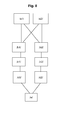
figure 8 représente les étapes d'un procédé mis en oeuvre selon l'invention.
- the
figure 1 schematically illustrates a kinematic chain equipped with sensors and monitored by a kinematic chain monitoring system according to one embodiment of the invention, - the
figure 2 shows a diagram of the kinematic chain monitoring system implemented on the kinematic chain of thefigure 1 , - the
figure 3 shows a graph illustrating the detection of the overspeed condition, - the
figure 4 shows a chronogram illustrating the detection of the desynchronism condition, - the
figure 5 shows a timing diagram illustrating the detection of static and dynamic deviation conditions, - the
figure 6 shows a winch system for handling loads according to a particular embodiment of the invention, - the
figure 7 illustrates a diagram of the surveillance system implemented in the system illustrated on thefigure 6 , - the
figure 8 represents the steps of a method implemented according to the invention.
Sur les différentes figures, les mêmes références désignent des éléments identiques ou similaires.In the different figures, the same references designate identical or similar elements.
En référence à la
L'arbre primaire 11 peut aussi être considéré comme l'arbre d'entrée de la chaine cinématique et l'arbre secondaire 12 est alors considéré comme l'arbre de sortie de la chaine cinématique.The
La chaine cinématique comprend en outre une transmission 2 qui relie l'arbre primaire 11 à l'arbre secondaire 12. Cette transmission peut comprendre un ou plusieurs train(s) d'engrenages, et peut comprendre le cas échéant aussi un accouplement élastique ou embrayage. Le ou les train(s) d'engrenages peuvent être des engrenages de type parallèle, conique ou planétaire. L'accouplement élastique, s'il est présent, permet d'encaisser des changements rapides ou brutaux de la vitesse angulaire de l'un des arbres.The kinematic chain further comprises a
La transmission présente un rapport de transmission noté K, rapport entre la vitesse de sortie (arbre secondaire) et la vitesse d'entrée (arbre primaire).The transmission has a transmission ratio denoted K, ratio between the output speed (secondary shaft) and the input speed (primary shaft).
Le système de surveillance comprend par ailleurs au moins un premier capteur 21 apte à délivrer au moins un premier signal 41 représentatif de la vitesse et du sens de rotation de l'arbre primaire 11. De plus, le système de surveillance comprend au moins un deuxième capteur 22 apte à délivrer au moins un deuxième signal 42 représentatif de la vitesse et du sens de rotation de l'arbre secondaire 12. Ces premier et deuxième capteurs 21,22 sont de préférence du type codeur à impulsions (aussi appelé 'codeur incrémental'). En particulier, on pourra choisir de préférence un type de codeur à impulsions permettant de détecter le sens de rotation, par exemple un codeur incrémental délivrant deux signaux décalés à 90° (i.e. en 'quadrature'). Ce type de codeur incrémental délivre des impulsions dont la fréquence est proportionnelle à la vitesse de déplacement de l'arbre en rotation. Chaque capteur peut comprendre deux rangées de repères, par exemple magnétiques ou optiques, par exemple plusieurs dizaines de repères par tour, ce qui permet de délivrer des signaux comportant un nombre important d'impulsions par tour. Ce type de capteur est relativement courant, fiable et peu onéreux.The surveillance system also includes less a
En référence à la
Grâce à la lecture de ces signaux, en fonction de l'analyse de ces premier et deuxième signaux 41,42, la première unité de surveillance 31 peut alors calculer la position angulaire de chacun des arbres primaire et secondaire par comptage des impulsions reçues.By reading these signals, as a function of the analysis of these first and
On notera la vitesse de l'arbre primaire par V1, la vitesse de l'arbre secondaire par V2, la position de l'arbre primaire par θ1 et la position de l'arbre secondaire par θ2. Toutes ces valeurs évoluent avec le temps t lors des mouvements des arbres.Note the speed of the primary shaft by V1, the speed of the secondary shaft by V2, the position of the primary shaft by θ1 and the position of the secondary shaft by θ2. All these values change with the time t during tree movements.
La première unité de surveillance 31 peut comparer les positions et vitesses de rotation des arbres primaire et secondaire 11,12 par rapport à des critères de bon fonctionnement prédéterminés qui seront explicités plus loin.The
La première unité de surveillance 31 peut alors commander au moins une première sortie 51 en réponse à un dysfonctionnement si les critères de bon fonctionnement ne sont pas respectés. Dans l'exemple illustré, le système de surveillance commande la première sortie 51 dans un état qui correspond à un état de mise en sécurité du système, aussi appelé 'état de sécurité' par la suite.The
Dans une logique de 'sécurité positive', la première sortie 51 sera commandée dans un état dit 'activé' si les critères de bon fonctionnement prédéterminés sont respectés et sera commandée dans un état inactif en cas de détection d'un dysfonctionnement. Ainsi, selon la logique en question, un apport d'énergie de commande autorisera le fonctionnement ou le déplacement et une absence d'énergie de commande s'opposera au déplacement.In a logic of "positive security", the
De plus, par souci de redondance, le système de surveillance comprend une deuxième unité de surveillance 32, similaire à la première, apte à acquérir les premier et deuxième signaux 41,42. Grâce à la lecture de ces signaux, la deuxième unité de surveillance 32 peut alors calculer de son côté les positions angulaires des arbres primaire et secondaire par comptage des impulsions reçues, de façon similaire à ce qui a été décrit pour la première unité de surveillance ci-dessus.In addition, for the sake of redundancy, the monitoring system comprises a
La deuxième unité de surveillance 32 peut alors comparer les positions et vitesses de rotation des arbres primaire et secondaire par rapport aux critères de bon fonctionnement prédéterminés déjà mentionnés ci dessus. La deuxième unité de surveillance 32 peut alors commander au moins une deuxième sortie 52 dans état de sécurité si les critères de bon fonctionnement ne sont pas respectés, de façon similaire à la première unité 31.The
Les première et deuxième unités de surveillance 31,32 peuvent être des automates programmables ou des moniteurs plus spécialisés. On pourra choisir à titre d'exemple un modèle de type 'Motrona' MS640.The first and
Les premier et deuxième capteurs 21,22 sont reliés aux unités de surveillance par des conducteurs 67 et 68 (cf.
Enfin, le système de surveillance comprend un circuit de sortie 33, apte à acquérir lesdits première et deuxième sorties 51,52. Le circuit de sortie 33 commande au moins une troisième sortie 53 dans un état de mise en sécurité si au moins l'une des première et deuxième sorties 51,52 est en état de sécurité. Cette troisième sortie 53 sera par exemple une sortie dite 'à contact sec' isolée du reste du circuit, le contact étant ouvert, la troisième sortie 53 est en état de mise en sécurité.Finally, the monitoring system comprises an
On pourra choisir à titre d'exemple un modèle de type 'PNOZ X5' commercialisé par la firme 'PILZ' pour former le circuit de sortie 33.We can choose as an example model 'PNOZ X5' marketed by the firm 'PILZ' to form the
Le système de surveillance peut aussi comprendre en outre la prise en compte de plusieurs ordres de mouvements 25,26,27 relatifs à une commande de motorisation de l'arbre primaire. Des entrées représentatives desdits ordres de mouvements 25,26,27 sont acquises par les première et deuxième unités de surveillance 31,32. Ainsi chacune des première et deuxième unités de surveillance 31,32 a connaissance d'un ordre de rotation dans un sens ou dans l'autre (Ctrl1 Ctrl2) sur l'arbre primaire 11.The monitoring system may also comprise the taking into account of several orders of
De plus, chacune des première et deuxième unités de surveillance 31,32 peut avoir connaissance d'une commande de grande vitesse (Ctrl3). De la sorte, les critères de bon fonctionnement prédéterminés pourront comporter la vérification du sens de rotation et l'adaptation de seuils de vitesse à ne pas dépasser, comme il sera précisé dans la suite.In addition, each of the first and
Les critères de bon fonctionnement peuvent par exemple comporter les critères ou conditions qui sont décrites ci-après en regard des dysfonctionnements potentiels correspondants.The operating criteria may, for example, include the criteria or conditions that are described below with regard to the corresponding potential malfunctions.
La condition de 'Survitesse' signifie que les arbres primaire et/ou secondaire 11,12 se mettent à tourner avec une vitesse de rotation supérieure à celle qui est normalement attendue. Il peut y avoir plusieurs seuils de vitesse qui représentent chacun une vitesse maximum attendue. On vérifiera donc parmi les critères de bon fonctionnement l'absence de survitesse.The condition of 'overspeed' means that the primary and / or
En référence à la
Un premier seuil de vitesse (repéré par 65 pour V1 et 66 pour V2) peut correspondre par exemple à la vitesse maximum attendue en opération à petite vitesse de la chaine cinématique (par exemple Ctrl3 non actif). Un second seuil de vitesse (repéré par 63 pour V1 et 64 pour V2) peut correspondre par exemple à la vitesse maximum attendue en opération à grande vitesse de la chaine cinématique (par exemple Ctrl3 actif). Dans l'exemple illustré, les seuils sont de signe contraire dans les deux sens de rotation, à savoir V1 et V2 positifs ou V1 et V2 négatifs.A first speed threshold (indicated by 65 for V1 and 66 for V2) can correspond for example to the maximum speed expected in low speed operation of the kinematic chain (for example Ctrl3 not active). A second speed threshold (indicated by 63 for V1 and 64 for V2) can correspond, for example, to the maximum speed expected during high speed operation of the kinematic chain (for example active Ctrl3). In the example illustrated, the thresholds are of opposite sign in the two directions of rotation, namely V1 and V2 positive or V1 and V2 negative.
Un exemple de courbe de vitesse est représenté par la courbe 60 sur la
La condition de 'désynchronisme' signifie que l'évolution des positions angulaires θ1, θ2 des arbres primaire et secondaire n'est plus en cohérence avec le rapport de transmission K de la transmission. Dans un fonctionnement normal, on constate sensiblement l'égalité θ2 = K.θ1 (on a aussi V2=K.V1 repéré 60 comme illustré sur la
En référence à la
Si cette valeur θ2-K.θ1 s'éloigne trop de la valeur nulle, et vient à dépasser une valeur seuil illustré par la valeur 81 sur la figure, comme par exemple à l'endroit du repère 80a, alors la condition de désynchronisme est déclarée par les unités de surveillance 31,32 qui commandent leurs sorties respectives 51,52. Le circuit de sortie 33 commande sa sortie (la troisième sortie 53) dans un état de mise en sécurité.If this value θ2-K.θ1 moves too far from the zero value, and comes to exceed a threshold value illustrated by the
Le dispositif en aval provoque alors la mise en sécurité de la chaine cinématique comme dans le cas précédent. Il est à noter qu'il suffit qu'une seule des unités de surveillance 31,32 commande sa sortie pour conduire à ce résultat.The downstream device then causes the setting safety of the kinematic chain as in the previous case. It should be noted that it suffices that only one of the
La zone de fonctionnement normal 82 est délimitée de chaque coté, positif et négatif, par la valeur seuil 81 déjà mentionnée. On peut donc aussi dire que la condition de désynchronisme est atteinte lorsque la valeur absolue de θ2-K.θ1 dépasse la valeur prédéterminée 81.The
Il est à noter que les conditions de survitesse et désynchronisme ne dépendent pas des ordres de mouvement de rotation sur l'arbre primaire, alors que les conditions de dévirage statique et dynamique décrites ci-après utilisent les ordres de mouvement (Ctrl1 Ctrl2) de rotation sur l'arbre primaire.It should be noted that the conditions of overspeed and desynchronism do not depend on the rotational motion commands on the primary shaft, whereas the static and dynamic unsteady conditions described below use the movement orders (Ctrl1 Ctrl2) of rotation on the primary shaft.
La condition de dévirage statique signifie que l'arbre secondaire 12 se met à tourner en l'absence de commande de rotation sur l'arbre primaire 11. On vérifiera donc parmi les critères de bon fonctionnement l'absence de dévirage statique.The condition of static deviation means that the
Une telle rotation inattendue peut intervenir juste après l'interruption d'un ordre de déplacement ou de manière permanente.Such an unexpected rotation may occur just after the interruption of a move order or permanently.
Comme illustré à la
La partie de chronogramme repérée 46 correspond à une phase de fonctionnement illustrant la détection de dévirage statique. A l'instant T6, lorsque la temporisation 97 est écoulée, la vitesse V2 n'est pas nulle (point repéré 91a), et donc la condition de dévirage statique est déclarée par les unités de surveillance 31,32 qui commandent alors leurs sorties respectives 51,52 à l'état de sécurité.The chronogram portion marked 46 corresponds to an operating phase illustrating the detection of static deviation. At the instant T6, when the
Un autre exemple est illustré à l'instant T7, aucun ordre de mouvement n'a été donné dans les instants précédents, et une rotation est détectée sur l'arbre secondaire (point repéré 91b). Alors la condition de dévirage statique est déclarée par les unités de surveillance 31,32 qui commandent alors leurs sorties respectives 51,52 à l'état de sécurité. Les unités de surveillance 31,32 utilisent les vitesses V1, V2 mais aussi les positions θ1,θ2. Another example is illustrated at time T7, no movement order was given in the previous instants, and a rotation is detected on the secondary shaft (marked
La condition de dévirage dynamique signifie que l'arbre secondaire 12 se met à tourner dans un sens opposé au sens de commande de rotation sur l'arbre primaire 11. On vérifiera donc parmi les critères de bon fonctionnement l'absence de dévirage dynamique.The dynamic unwinding condition means that the
La partie de chronogramme repérée 47 correspond à une phase de fonctionnement illustrant la détection de dévirage dynamique. Après un début de séquence similaire à la séquence normale, à l'instant T8, lorsque la commande 98 intervient, la vitesse V2 s'écarte de 0 avec des valeurs de signe opposé à celui qui est attendu (point repéré 92a). Alors la condition de dévirage dynamique est déclarée par les unités de surveillance 31,32 qui commandent alors leurs sorties respectives 51,52 à l'état de sécurité.The identified
Les unités de surveillance 31,32 utilisent les vitesses V1, V2 mais aussi les positions θ1, θ2. The
Il est à noter que à partir de la surveillance des positions et des vitesses, on obtient des temps de réponse performants pour déclarer un dysfonctionnement, par exemple des temps de réponse inférieurs à 100 ms.It should be noted that from the monitoring of the positions and speeds, we obtain efficient response times to declare a malfunction, for example response times less than 100 ms.
De façon optionnelle, comme illustré à la
Ce troisième capteur 23 est apte à délivrer un signal 43 représentatif de la vitesse et du sens de rotation de l'arbre primaire, formant un signal redondant du premier signal 41 représentatif de la vitesse et du sens de rotation de l'arbre primaire et qui est lu par la deuxième unité de surveillance 32.This
Les signaux 41,43 forment ainsi des premiers signaux représentatifs de la vitesse et du sens de rotation de l'arbre primaire 11.The
Le quatrième capteur 24 est apte à délivrer un signal 44 représentatif de la vitesse et du sens de rotation de l'arbre secondaire, formant un signal redondant du deuxième signal 42 représentatif de la vitesse et du sens de rotation de l'arbre secondaire et qui est lu par la première unité de surveillance 31.The
Les signaux 42,44 forment ainsi des deuxièmes signaux représentatifs de la vitesse et du sens de rotation de l'arbre secondaire 12.The
Il s'ensuit qu'une défaillance d'un des capteurs 21-24 peut être tolérée sans que cela affecte la fonction du système de surveillance. En conséquence de quoi, une défaillance d'un des capteurs 21-24 ne dégrade pas la fonction de surveillance du système.As a result, a failure of one of the sensors 21-24 can be tolerated without affecting the function of the monitoring system. As a result, failure of one of the sensors 21-24 does not degrade the system monitoring function.
Il est à noter que le schéma des capteurs redondants de la
En référence à la
Par ailleurs, le système de treuil comprend une chaine cinématique telle que décrite précédemment, notamment un support 90, constituant le bâti du système de treuil, un arbre primaire 11 (appelé ici arbre 'rapide') pivotant autour d'un axe X, un arbre secondaire 12 (appelé ici arbre 'lent') pivotant autour d'un axe Y, le tambour 5 susmentionné étant fixé à l'arbre secondaire 12.Furthermore, the winch system comprises a kinematic chain as described above, in particular a
Par ailleurs, le système de treuil comprend au moins un dispositif de frein 61,62 apte à agir sur au moins un organe de frein 71,72 lié à l'arbre primaire 11 ou à l'arbre secondaire 12.Moreover, the winch system comprises at least one
En l'occurrence, dans l'exemple illustré, le dispositif de frein en question comprend un premier dispositif de frein 61 apte à agir sur un premier organe de frein 71 lié au tambour et solidaire du tambour en rotation, ledit premier organe de frein 71 étant ici un disque de frein comme connu dans l'art.In this case, in the example illustrated, the brake device in question comprises a
Un dispositif d'entrainement, monté sur le support 90, est prévu pour entrainer l'arbre primaire 11 en rotation. Ce dispositif d'entrainement comprend un organe moteur 4 de préférence de type moteur électrique asynchrone.A drive device, mounted on the
Selon un aspect avantageux, l'arbre primaire (rapide) 11 peut comprendre un deuxième organe de frein 72, dans l'exemple représenté sous la forme d'un disque de frein. Un deuxième dispositif de frein 62 est agencé en vis-à-vis de ce deuxième organe de frein 72 et est apte à agir sur lui.According to an advantageous aspect, the (fast)
Le premier dispositif de frein 61, tout comme le deuxième dispositif de frein 62 lorsqu'il est présent, peuvent se présenter comme un étrier à mâchoires mobiles pourvu de plaquettes de friction. Le déplacement des mâchoires est commandé de préférence électriquement, bien qu'une commande hydraulique ou autre peut être tout aussi bien envisagée.The
De préférence et de manière avantageuse selon le principe de sécurité positive, les mâchoires serrent le disque en vis-à-vis lorsque un courant de commande faible ou nul est appliqué, ce qui est appelé dans le métier un frein à manque de courant.Preferably and advantageously according to the principle of positive safety, the jaws clamp the disc vis-à-vis when a low or zero control current is applied, which is called in the trade a brake power failure.
Il peut y avoir, sans que cela ne soit nécessaire à la réalisation de la présente invention, un second dispositif d'entrainement comprenant une transmission 2B auquel cas on parle de 'système fermé'. Il peut y avoir aussi le cas échéant un deuxième moteur 4B.There may be, without this being necessary for the realization of the present invention, a second training device comprising a
La
Un circuit de commande 3 acquiert les ordres de mouvements 25,26,27 et pilote l'organe moteur 4.A
Concernant les ordres de mouvements 25,26,27, deux ordres de base 'Ctrl1' et 'Ctrl2' correspondent respectivement aux ordres de 'Montée' et 'Descente'. En outre, le troisième ordre de mouvement 27 correspond à un changement de consigne de vitesse (par exemple une commande de grande vitesse 'G.V').Concerning the orders of
La première sortie 51 est connectée à un premier relais 81 faisant partie du circuit de sortie 33.The
La deuxième sortie 52 est connectée à un deuxième relais 82 faisant aussi partie du circuit de sortie 33. Les sorties 'contacts secs' des premier et deuxième relais 81,82 sont raccordées en mode série pour donner une troisième sortie 53. Cette troisième sortie 53 commande l'organe magnétique 61a du premier dispositif de frein 61 et commande simultanément l'organe magnétique 62a du second dispositif de frein 62 notamment afin de sauvegarder l'intégrité mécanique de la transmission 2. En effet, l'inertie du rotor du moteur 4 peut être relativement importante et l'activation du deuxième dispositif de frein 62 permet de dissiper l'énergie cinétique du rotor.The
Il peut y avoir en outre un troisième relais 83 disposé en série sur le circuit de sortie, en provenance d'un circuit d'arrêt d'urgence par exemple.There may also be a
Un signal 85 dérivé de la troisième sortie peut informer le circuit de commande 3 du déclenchement de la sécurité. Un réarmement sera nécessaire pour remettre en service le treuil après un déclenchement de la sécurité.A
La
- /a1/ délivrer, au niveau du premier capteur, au moins un des premiers signaux 41;43 représentatif de la vitesse et du sens de rotation de l'arbre primaire 11,
- /a2/ délivrer, au niveau du deuxième capteur, au moins un des deuxièmes signaux 42;44 représentatif de la vitesse et du sens de rotation de l'arbre
secondaire 12, - /b1/ acquérir, au niveau de la première unité de
surveillance 31 au moins deux des premier et deuxième signaux 41,42;44, et calculer les positions angulaires des arbres primaire et secondaire, - /c1/ comparer, dans la première unité de
surveillance 31, les positions et vitesses de rotation des arbres primaire et secondaire par rapport à des critères de bon fonctionnement prédéterminés, - /d1/ commander, par la première unité de
surveillance 31, au moins une première sortie 51 dans un état de sécurité si les critères de bon fonctionnement ne sont pas respectés, - /b2/ acquérir, au niveau de la deuxième unité de
surveillance 32 au moins deux des premier et deuxième signaux 41;43,42, et calculer les positions angulaires des arbres primaire et secondaire, - /c2/ comparer dans la deuxième unité de
surveillance 32, les positions et vitesses de rotation des arbres primaire et secondaire par rapport à des critères de bon fonctionnement prédéterminés, - /d2/ commander, par la deuxième unité de
surveillance 32, au moins une deuxième sortie 52 dans un état de sécurité si les critères de bon fonctionnement ne sont pas respectés. - /e/ commander au moins une troisième sortie 53 dans un état de mise en sécurité si au moins l'une des première et deuxième
sorties
- / a1 / delivering, at the first sensor, at least one of the
first signals 41; 43 representative of the speed and direction of rotation of theprimary shaft 11, - / a2 / delivering, at the second sensor, at least one of the second signals 42; 44 representative of the speed and direction of rotation of the
secondary shaft 12, - / b1 / acquiring, at the
first monitoring unit 31 at least two of the first andsecond signals - / c1 / compare, in the
first monitoring unit 31, the positions and speeds of rotation of the primary and secondary shafts with respect to predetermined operating criteria, - / d1 / control, by the
first monitoring unit 31, at least afirst output 51 in a safe state if the operating criteria are not met, - / b2 / acquiring, at the level of the
second monitoring unit 32 at least two of the first andsecond signals 41; 43,42, and calculating the angular positions of the primary and secondary shafts, - / c2 / comparing in the
second monitoring unit 32, the positions and speeds of rotation of the primary and secondary shafts with respect to predetermined operating criteria, - / d2 / control, by the
second monitoring unit 32, at least asecond output 52 in a safe state if the operating criteria are not met. - / e / controlling at least a
third output 53 in a safe state if at least one of the first andsecond outputs
Il est à noter que les étapes /a1/ et /a2/ peuvent être réalisées en parallèle. De même, la branche des étapes /b1/-/c1/-/d1/ peut être réalisée en parallèle de la branche des étapes /b2/-/c2/-/d2/.It should be noted that the steps / a1 / and / a2 / can be performed in parallel. Similarly, the branch of steps / b1 / - / c1 / - / d1 / can be performed in parallel with the branch of steps / b2 / - / c2 / - / d2 /.
Les critères de bon fonctionnement prédéterminés correspondent à ceux décrits précédemment avec leurs raffinements éventuels. En particulier, tout comme décrit précédemment, la comparaison effectuée aux étapes /c1/ et /c2/ peut prendre en compte, notamment pour le dévirage statique et le dévirage dynamique, les ordres de mouvements 25,26,27 relatifs à la commande de motorisation de l'arbre primaire.The predetermined operating criteria correspond to those previously described with their possible refinements. In particular, as described above, the comparison made in steps / c1 / and / c2 / can take into account, in particular for the static deviation and the dynamic deviation, the movement orders 25,26,27 relating to the motor control of the primary shaft.
Claims (11)
et comprenant en outre:
and further comprising:
le procédé comprenant les étapes :
the process comprising the steps:
Priority Applications (1)
| Application Number | Priority Date | Filing Date | Title |
|---|---|---|---|
| PL12193457T PL2602601T3 (en) | 2011-12-09 | 2012-11-20 | System for monitoring a drive train |
Applications Claiming Priority (1)
| Application Number | Priority Date | Filing Date | Title |
|---|---|---|---|
| FR1161427A FR2983957B1 (en) | 2011-12-09 | 2011-12-09 | CINEMATIC CHAIN MONITORING SYSTEM |
Publications (2)
| Publication Number | Publication Date |
|---|---|
| EP2602601A1 true EP2602601A1 (en) | 2013-06-12 |
| EP2602601B1 EP2602601B1 (en) | 2015-10-21 |
Family
ID=46785455
Family Applications (1)
| Application Number | Title | Priority Date | Filing Date |
|---|---|---|---|
| EP12193457.4A Active EP2602601B1 (en) | 2011-12-09 | 2012-11-20 | System for monitoring a drive train |
Country Status (4)
| Country | Link |
|---|---|
| EP (1) | EP2602601B1 (en) |
| ES (1) | ES2557447T3 (en) |
| FR (1) | FR2983957B1 (en) |
| PL (1) | PL2602601T3 (en) |
Citations (3)
| Publication number | Priority date | Publication date | Assignee | Title |
|---|---|---|---|---|
| EP0430297A2 (en) * | 1989-11-30 | 1991-06-05 | Meidensha Kabushiki Kaisha | Method and system for testing specimen of automotive power transmission connected to engine and analyzing engine output characteristic via specimen tested using dynamometer |
| EP1116665A1 (en) * | 2000-01-11 | 2001-07-18 | TOPACK Verpackungstechnik GmbH | Method for monitoring the wear of a driving system as well as the driving system of a machine for the tabacco processing industry |
| US6526816B2 (en) | 2000-12-13 | 2003-03-04 | Eaton Corporation | Transmission gear life monitor system |
-
2011
- 2011-12-09 FR FR1161427A patent/FR2983957B1/en active Active
-
2012
- 2012-11-20 PL PL12193457T patent/PL2602601T3/en unknown
- 2012-11-20 EP EP12193457.4A patent/EP2602601B1/en active Active
- 2012-11-20 ES ES12193457.4T patent/ES2557447T3/en active Active
Patent Citations (3)
| Publication number | Priority date | Publication date | Assignee | Title |
|---|---|---|---|---|
| EP0430297A2 (en) * | 1989-11-30 | 1991-06-05 | Meidensha Kabushiki Kaisha | Method and system for testing specimen of automotive power transmission connected to engine and analyzing engine output characteristic via specimen tested using dynamometer |
| EP1116665A1 (en) * | 2000-01-11 | 2001-07-18 | TOPACK Verpackungstechnik GmbH | Method for monitoring the wear of a driving system as well as the driving system of a machine for the tabacco processing industry |
| US6526816B2 (en) | 2000-12-13 | 2003-03-04 | Eaton Corporation | Transmission gear life monitor system |
Also Published As
| Publication number | Publication date |
|---|---|
| FR2983957B1 (en) | 2014-01-24 |
| PL2602601T3 (en) | 2016-04-29 |
| ES2557447T3 (en) | 2016-01-26 |
| FR2983957A1 (en) | 2013-06-14 |
| EP2602601B1 (en) | 2015-10-21 |
Similar Documents
| Publication | Publication Date | Title |
|---|---|---|
| EP2623748B1 (en) | Method and device for monitoring the health of a turbine engine of an aircraft provided with at least one turbine engine | |
| EP3712059B1 (en) | Method and device for displacing a centre of gravity of an aircraft | |
| EP2293429B1 (en) | Secured surveillance and control device for an aircraft handling actuator | |
| EP3702269B1 (en) | A haptic alert mechanism for alerting an aircraft pilot, and an aircraft | |
| EP2551191A1 (en) | Method and device for detecting the deployment of an aircraft control surface. | |
| FR3009540A1 (en) | ||
| FR2713193A1 (en) | Method and device for detecting an overshoot of the design loads of an aircraft | |
| FR3012112A1 (en) | METHOD FOR MONITORING THE OPERATION OF AN AIRCRAFT DRIVING DEVICE AND AIRCRAFT DRIVING DEVICE SO MONITORED | |
| EP2902285B1 (en) | Method for monitoring at least two electromechanical braking actuators | |
| CA2980295A1 (en) | Electric control element, rotorcraft and process | |
| FR2986398A1 (en) | SAFETY DEVICE FOR CONTROLLING AN ENGINE COMPRISING A REDUNDANCY OF ACQUISITIONS OF A SENSOR MEASUREMENT | |
| EP2602601B1 (en) | System for monitoring a drive train | |
| EP1912103B1 (en) | Method and device for supervising the servo function of an actuator | |
| EP2254791B1 (en) | Method and system for deactivating the orientation system of the front landing gear of an aircraft | |
| EP2894070A1 (en) | Method for monitoring a blocking member, and electromehanical actuator | |
| FR3050309B1 (en) | NUCLEAR REACTOR ABSORBENT DRIVE MECHANISM, MONITORING METHOD AND CORRESPONDING NUCLEAR REACTOR | |
| FR2975076A1 (en) | ADJUSTING DEVICE, IN PARTICULAR ADJUSTING DEVICE FOR AN AIRCRAFT | |
| EP2603922B1 (en) | Method and device for controlling the movement of a movable member of a disconnecting switch | |
| EP3227981B1 (en) | Detection method of the blocking of a rotor of an engine moving an actuating member | |
| EP2762434B1 (en) | System for controlling and limiting speed for monitoring the movement of a movable member | |
| FR3086644A1 (en) | METHOD FOR DETECTING THE BLOCKING OF AT LEAST ONE AIRWAY OF A AIRCRAFT AND ASSOCIATED SYSTEM | |
| WO2012120248A1 (en) | Method and device for controlling the electric motor of a windshield wiper | |
| FR2956881A1 (en) | Changing angle controlling-ordering system for blades of wind turbine i.e. aerogenerator type wind turbine, connected to electric network, has contactor closure arranged for stopping functioning of variator | |
| FR3130469A1 (en) | Device for disconnecting a generator driven by a rotor, associated generator-motor assembly. | |
| FR2875254A1 (en) | METHOD FOR CONTROLLING THE OPERATION OF A QUICK DOOR |
Legal Events
| Date | Code | Title | Description |
|---|---|---|---|
| PUAI | Public reference made under article 153(3) epc to a published international application that has entered the european phase |
Free format text: ORIGINAL CODE: 0009012 |
|
| AK | Designated contracting states |
Kind code of ref document: A1 Designated state(s): AL AT BE BG CH CY CZ DE DK EE ES FI FR GB GR HR HU IE IS IT LI LT LU LV MC MK MT NL NO PL PT RO RS SE SI SK SM TR |
|
| AX | Request for extension of the european patent |
Extension state: BA ME |
|
| 17P | Request for examination filed |
Effective date: 20131212 |
|
| RBV | Designated contracting states (corrected) |
Designated state(s): AL AT BE BG CH CY CZ DE DK EE ES FI FR GB GR HR HU IE IS IT LI LT LU LV MC MK MT NL NO PL PT RO RS SE SI SK SM TR |
|
| GRAP | Despatch of communication of intention to grant a patent |
Free format text: ORIGINAL CODE: EPIDOSNIGR1 |
|
| INTG | Intention to grant announced |
Effective date: 20150508 |
|
| GRAS | Grant fee paid |
Free format text: ORIGINAL CODE: EPIDOSNIGR3 |
|
| GRAA | (expected) grant |
Free format text: ORIGINAL CODE: 0009210 |
|
| AK | Designated contracting states |
Kind code of ref document: B1 Designated state(s): AL AT BE BG CH CY CZ DE DK EE ES FI FR GB GR HR HU IE IS IT LI LT LU LV MC MK MT NL NO PL PT RO RS SE SI SK SM TR |
|
| REG | Reference to a national code |
Ref country code: GB Ref legal event code: FG4D Free format text: NOT ENGLISH |
|
| REG | Reference to a national code |
Ref country code: CH Ref legal event code: EP |
|
| REG | Reference to a national code |
Ref country code: AT Ref legal event code: REF Ref document number: 756897 Country of ref document: AT Kind code of ref document: T Effective date: 20151115 |
|
| REG | Reference to a national code |
Ref country code: IE Ref legal event code: FG4D Free format text: LANGUAGE OF EP DOCUMENT: FRENCH |
|
| REG | Reference to a national code |
Ref country code: DE Ref legal event code: R096 Ref document number: 602012011756 Country of ref document: DE |
|
| REG | Reference to a national code |
Ref country code: FR Ref legal event code: PLFP Year of fee payment: 4 |
|
| REG | Reference to a national code |
Ref country code: RO Ref legal event code: EPE |
|
| REG | Reference to a national code |
Ref country code: ES Ref legal event code: FG2A Ref document number: 2557447 Country of ref document: ES Kind code of ref document: T3 Effective date: 20160126 |
|
| REG | Reference to a national code |
Ref country code: LT Ref legal event code: MG4D |
|
| REG | Reference to a national code |
Ref country code: NL Ref legal event code: FP |
|
| REG | Reference to a national code |
Ref country code: AT Ref legal event code: MK05 Ref document number: 756897 Country of ref document: AT Kind code of ref document: T Effective date: 20151021 |
|
| PG25 | Lapsed in a contracting state [announced via postgrant information from national office to epo] |
Ref country code: HR Free format text: LAPSE BECAUSE OF FAILURE TO SUBMIT A TRANSLATION OF THE DESCRIPTION OR TO PAY THE FEE WITHIN THE PRESCRIBED TIME-LIMIT Effective date: 20151021 Ref country code: NO Free format text: LAPSE BECAUSE OF FAILURE TO SUBMIT A TRANSLATION OF THE DESCRIPTION OR TO PAY THE FEE WITHIN THE PRESCRIBED TIME-LIMIT Effective date: 20160121 Ref country code: IS Free format text: LAPSE BECAUSE OF FAILURE TO SUBMIT A TRANSLATION OF THE DESCRIPTION OR TO PAY THE FEE WITHIN THE PRESCRIBED TIME-LIMIT Effective date: 20160221 Ref country code: LT Free format text: LAPSE BECAUSE OF FAILURE TO SUBMIT A TRANSLATION OF THE DESCRIPTION OR TO PAY THE FEE WITHIN THE PRESCRIBED TIME-LIMIT Effective date: 20151021 |
|
| PG25 | Lapsed in a contracting state [announced via postgrant information from national office to epo] |
Ref country code: RS Free format text: LAPSE BECAUSE OF FAILURE TO SUBMIT A TRANSLATION OF THE DESCRIPTION OR TO PAY THE FEE WITHIN THE PRESCRIBED TIME-LIMIT Effective date: 20151021 Ref country code: LV Free format text: LAPSE BECAUSE OF FAILURE TO SUBMIT A TRANSLATION OF THE DESCRIPTION OR TO PAY THE FEE WITHIN THE PRESCRIBED TIME-LIMIT Effective date: 20151021 Ref country code: PT Free format text: LAPSE BECAUSE OF FAILURE TO SUBMIT A TRANSLATION OF THE DESCRIPTION OR TO PAY THE FEE WITHIN THE PRESCRIBED TIME-LIMIT Effective date: 20160222 Ref country code: SE Free format text: LAPSE BECAUSE OF FAILURE TO SUBMIT A TRANSLATION OF THE DESCRIPTION OR TO PAY THE FEE WITHIN THE PRESCRIBED TIME-LIMIT Effective date: 20151021 Ref country code: AT Free format text: LAPSE BECAUSE OF FAILURE TO SUBMIT A TRANSLATION OF THE DESCRIPTION OR TO PAY THE FEE WITHIN THE PRESCRIBED TIME-LIMIT Effective date: 20151021 Ref country code: GR Free format text: LAPSE BECAUSE OF FAILURE TO SUBMIT A TRANSLATION OF THE DESCRIPTION OR TO PAY THE FEE WITHIN THE PRESCRIBED TIME-LIMIT Effective date: 20160122 |
|
| REG | Reference to a national code |
Ref country code: CH Ref legal event code: PL |
|
| REG | Reference to a national code |
Ref country code: DE Ref legal event code: R097 Ref document number: 602012011756 Country of ref document: DE |
|
| PG25 | Lapsed in a contracting state [announced via postgrant information from national office to epo] |
Ref country code: MC Free format text: LAPSE BECAUSE OF FAILURE TO SUBMIT A TRANSLATION OF THE DESCRIPTION OR TO PAY THE FEE WITHIN THE PRESCRIBED TIME-LIMIT Effective date: 20151021 Ref country code: LI Free format text: LAPSE BECAUSE OF NON-PAYMENT OF DUE FEES Effective date: 20151130 Ref country code: CH Free format text: LAPSE BECAUSE OF NON-PAYMENT OF DUE FEES Effective date: 20151130 |
|
| REG | Reference to a national code |
Ref country code: IE Ref legal event code: MM4A |
|
| PLBE | No opposition filed within time limit |
Free format text: ORIGINAL CODE: 0009261 |
|
| STAA | Information on the status of an ep patent application or granted ep patent |
Free format text: STATUS: NO OPPOSITION FILED WITHIN TIME LIMIT |
|
| PG25 | Lapsed in a contracting state [announced via postgrant information from national office to epo] |
Ref country code: SM Free format text: LAPSE BECAUSE OF FAILURE TO SUBMIT A TRANSLATION OF THE DESCRIPTION OR TO PAY THE FEE WITHIN THE PRESCRIBED TIME-LIMIT Effective date: 20151021 Ref country code: DK Free format text: LAPSE BECAUSE OF FAILURE TO SUBMIT A TRANSLATION OF THE DESCRIPTION OR TO PAY THE FEE WITHIN THE PRESCRIBED TIME-LIMIT Effective date: 20151021 Ref country code: EE Free format text: LAPSE BECAUSE OF FAILURE TO SUBMIT A TRANSLATION OF THE DESCRIPTION OR TO PAY THE FEE WITHIN THE PRESCRIBED TIME-LIMIT Effective date: 20151021 Ref country code: SK Free format text: LAPSE BECAUSE OF FAILURE TO SUBMIT A TRANSLATION OF THE DESCRIPTION OR TO PAY THE FEE WITHIN THE PRESCRIBED TIME-LIMIT Effective date: 20151021 |
|
| 26N | No opposition filed |
Effective date: 20160722 |
|
| PG25 | Lapsed in a contracting state [announced via postgrant information from national office to epo] |
Ref country code: IE Free format text: LAPSE BECAUSE OF NON-PAYMENT OF DUE FEES Effective date: 20151120 |
|
| REG | Reference to a national code |
Ref country code: FR Ref legal event code: PLFP Year of fee payment: 5 |
|
| PG25 | Lapsed in a contracting state [announced via postgrant information from national office to epo] |
Ref country code: SI Free format text: LAPSE BECAUSE OF FAILURE TO SUBMIT A TRANSLATION OF THE DESCRIPTION OR TO PAY THE FEE WITHIN THE PRESCRIBED TIME-LIMIT Effective date: 20151021 |
|
| PG25 | Lapsed in a contracting state [announced via postgrant information from national office to epo] |
Ref country code: HU Free format text: LAPSE BECAUSE OF FAILURE TO SUBMIT A TRANSLATION OF THE DESCRIPTION OR TO PAY THE FEE WITHIN THE PRESCRIBED TIME-LIMIT; INVALID AB INITIO Effective date: 20121120 Ref country code: BG Free format text: LAPSE BECAUSE OF FAILURE TO SUBMIT A TRANSLATION OF THE DESCRIPTION OR TO PAY THE FEE WITHIN THE PRESCRIBED TIME-LIMIT Effective date: 20151021 |
|
| PG25 | Lapsed in a contracting state [announced via postgrant information from national office to epo] |
Ref country code: CY Free format text: LAPSE BECAUSE OF FAILURE TO SUBMIT A TRANSLATION OF THE DESCRIPTION OR TO PAY THE FEE WITHIN THE PRESCRIBED TIME-LIMIT Effective date: 20151021 |
|
| PG25 | Lapsed in a contracting state [announced via postgrant information from national office to epo] |
Ref country code: MT Free format text: LAPSE BECAUSE OF FAILURE TO SUBMIT A TRANSLATION OF THE DESCRIPTION OR TO PAY THE FEE WITHIN THE PRESCRIBED TIME-LIMIT Effective date: 20151021 |
|
| REG | Reference to a national code |
Ref country code: FR Ref legal event code: PLFP Year of fee payment: 6 |
|
| PG25 | Lapsed in a contracting state [announced via postgrant information from national office to epo] |
Ref country code: LU Free format text: LAPSE BECAUSE OF NON-PAYMENT OF DUE FEES Effective date: 20151120 |
|
| PG25 | Lapsed in a contracting state [announced via postgrant information from national office to epo] |
Ref country code: MK Free format text: LAPSE BECAUSE OF FAILURE TO SUBMIT A TRANSLATION OF THE DESCRIPTION OR TO PAY THE FEE WITHIN THE PRESCRIBED TIME-LIMIT Effective date: 20151021 |
|
| PG25 | Lapsed in a contracting state [announced via postgrant information from national office to epo] |
Ref country code: AL Free format text: LAPSE BECAUSE OF FAILURE TO SUBMIT A TRANSLATION OF THE DESCRIPTION OR TO PAY THE FEE WITHIN THE PRESCRIBED TIME-LIMIT Effective date: 20151021 |
|
| PGFP | Annual fee paid to national office [announced via postgrant information from national office to epo] |
Ref country code: PL Payment date: 20221018 Year of fee payment: 11 Ref country code: BE Payment date: 20221125 Year of fee payment: 11 |
|
| PGFP | Annual fee paid to national office [announced via postgrant information from national office to epo] |
Ref country code: NL Payment date: 20231023 Year of fee payment: 12 |
|
| PGFP | Annual fee paid to national office [announced via postgrant information from national office to epo] |
Ref country code: GB Payment date: 20231120 Year of fee payment: 12 |
|
| PGFP | Annual fee paid to national office [announced via postgrant information from national office to epo] |
Ref country code: ES Payment date: 20231218 Year of fee payment: 12 |
|
| PGFP | Annual fee paid to national office [announced via postgrant information from national office to epo] |
Ref country code: TR Payment date: 20231108 Year of fee payment: 12 Ref country code: RO Payment date: 20231101 Year of fee payment: 12 Ref country code: IT Payment date: 20231109 Year of fee payment: 12 Ref country code: FR Payment date: 20231023 Year of fee payment: 12 Ref country code: FI Payment date: 20231020 Year of fee payment: 12 Ref country code: DE Payment date: 20231107 Year of fee payment: 12 Ref country code: CZ Payment date: 20231020 Year of fee payment: 12 |
|
| PGFP | Annual fee paid to national office [announced via postgrant information from national office to epo] |
Ref country code: PL Payment date: 20231030 Year of fee payment: 12 Ref country code: BE Payment date: 20231113 Year of fee payment: 12 |